Delta X S V5 D800 Specifications
Basic Parameters
| Parameters | Specifications |
|---|---|
| Working space | D = 800 mm, H = 240mm |
| Max payload | 2 kg |
| Max speed | 3 m/s |
| Max accel | 50 m/s2 |
| Pose repeatability | ±0.15 mm |
| Position accuracy | ±0.15 mm |
| Number of axes | 3/4/5/6 |
| Power supply | 24VDC - 30A |
| Weight | 25 kg |
Electrical Parameters
| Components | Specifications |
|---|---|
| Controller Board | Delta X S Board (ARM Cortex-M7) |
| Communication | USB, UART, Etherner, RS232, RS485 |
| Input | 2 Analog Input, 4 Digital Input |
| Output | 8 Digital Output |
Mechanical materials
| Part | Materials |
|---|---|
| Upper Arm | Aluminum plate |
| Lower Arm | Carbon fibre tube |
| Base frame | Aluminum |
| Moving base | Aluminum |
| Motor mounted | Aluminum |
| Body cover | 3D printed (PLA) |
Working Space
Reach
Safe Working Area
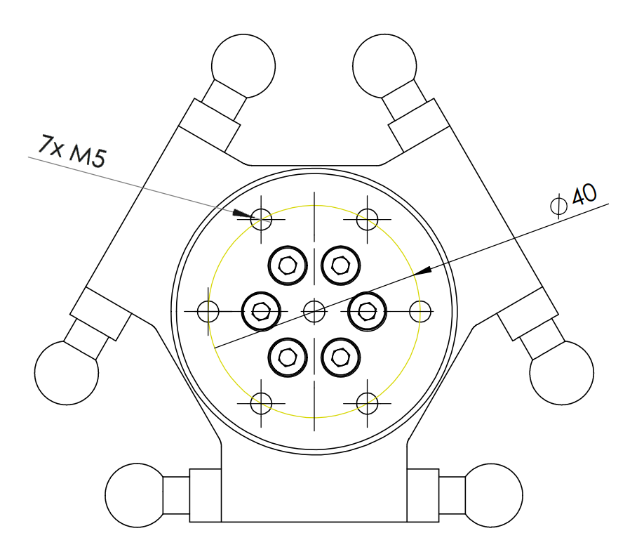
Moving Base Dimensions
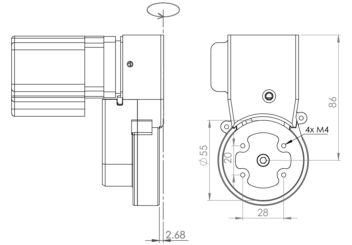
3-Axes Model
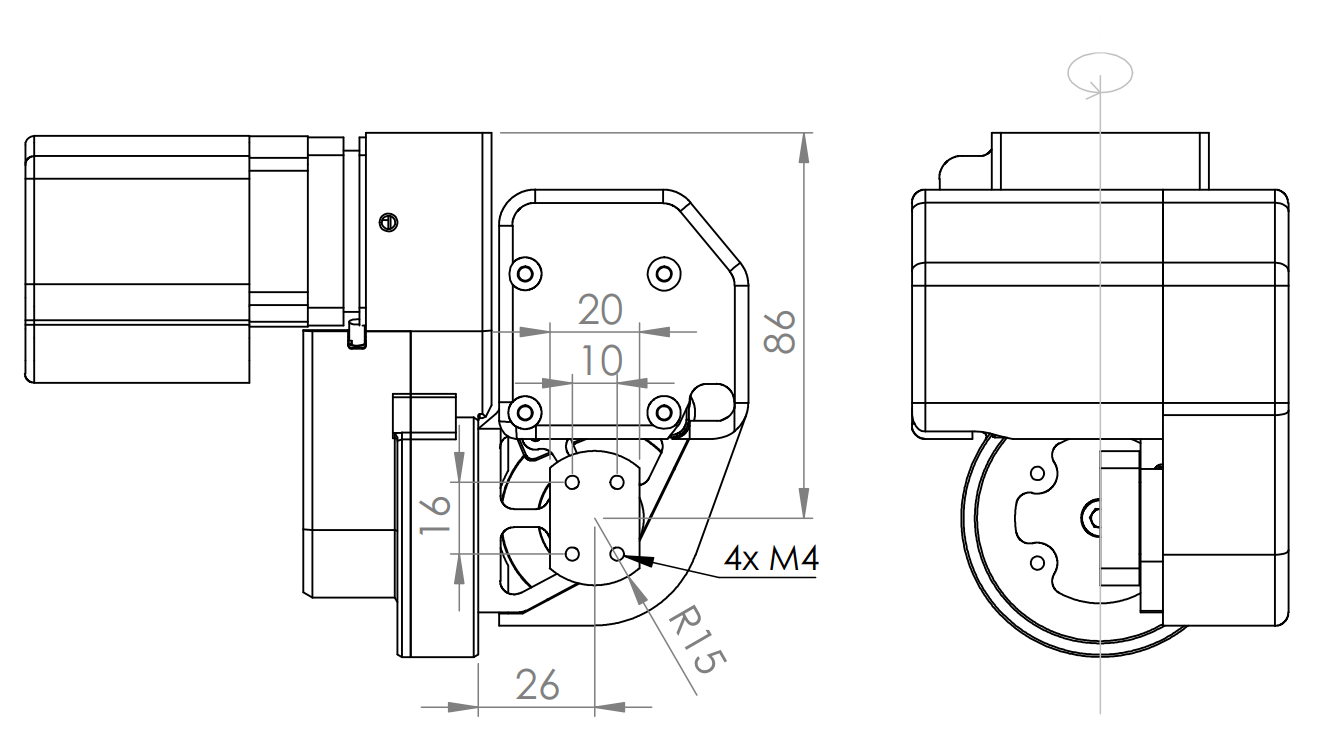
4-Axes Model
5-Axes Model
6-Axes Model
Wiring & Communication Ports
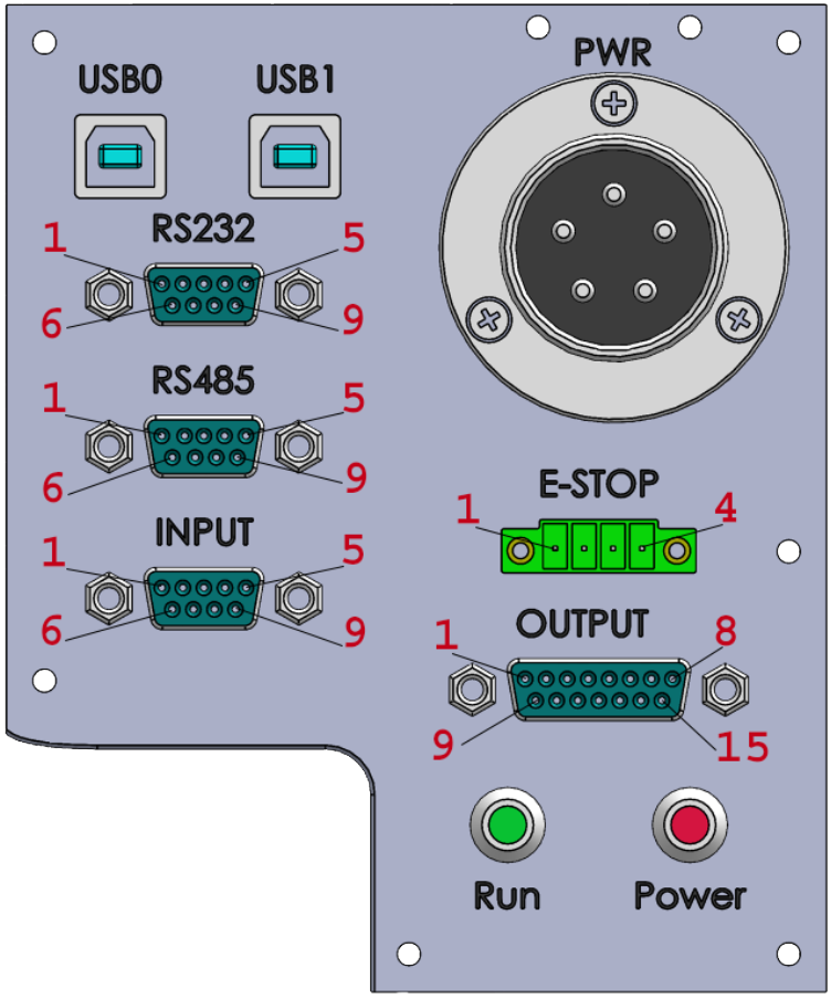
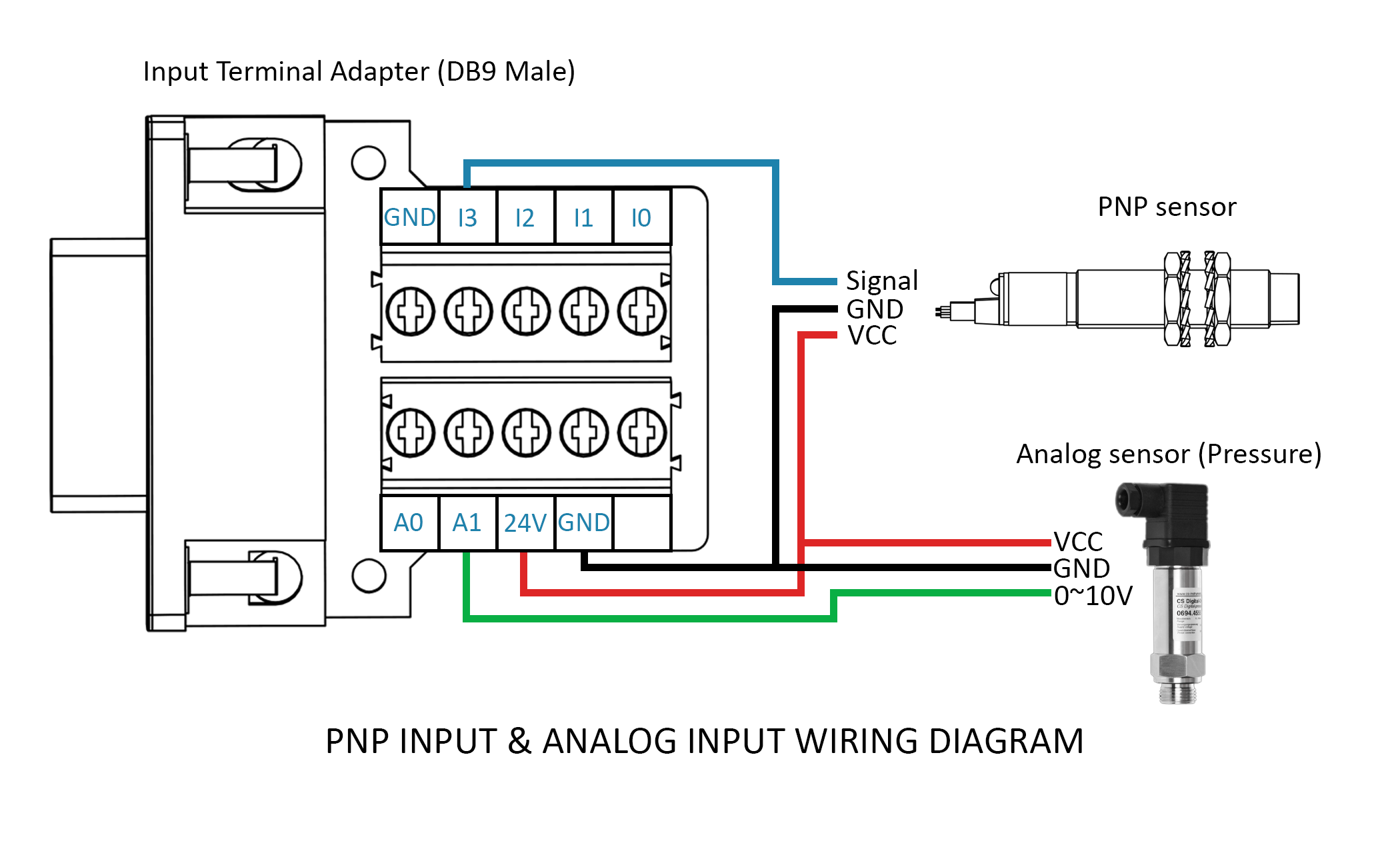
Digital INPUT pins (24VDC/3mA) & Analog input pins(0-10VDC/0-4096):
| INPUT PIN | |
|---|---|
| Pin 1 - I0 | Pin 6 - A0 |
| Pin 2 - I1 | Pin 7 - A1 |
| Pin 3 - I2 | Pin 8 - 24V |
| Pin 4 - I3 | Pin 9 - GND |
| Pin 5 - GND |
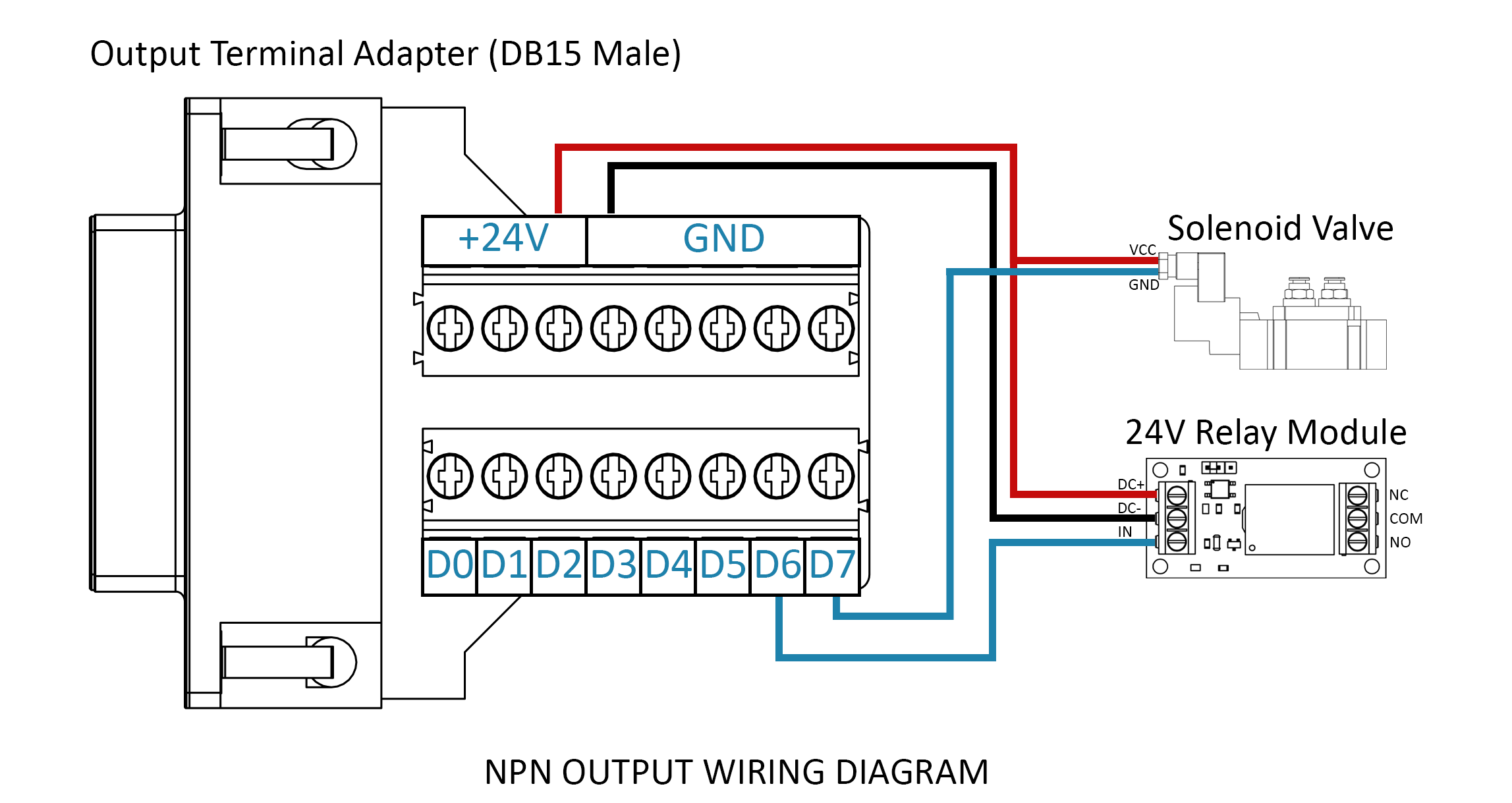
Digital OUPUT pins (24VDC/500mA):
| OUTPUT PIN | |||
|---|---|---|---|
| Pin 1 - D0 | Pin 2 - D1 | Pin 3 - D2 | Pin 4 - D3 |
| Pin 5 - D4 | Pin 6 - D5 | Pin 7 - D6 | Pin 8 - D7 |
| Pin 9~12 - 24VDC | Pin 12~15 - GND |
E-STOP pins:
| E-STOP PIN | |
|---|---|
| Pin 1 - GND | Pin 2 - I4 |
| Pin 3 - I5 | Pin 4 - 24V |
Input Terminal Adapter (DB9 Male) and Wiring Example
Output Terminal Adapter (DB15 Male) and Wiring Example
If emergency button is not enabled, IN4 and IN5 can be use as input pin.
NOTE: Connect any output as shown above, do not load more than 500mA for each output pin.
Contact Us
- Store: https://deltaxstore.com
- Website: https://www.deltaxrobot.com
- Email: deltaxrobot@gmail.com
- Phone: +84 38 875 2005